SolidWorks CAD: Power steering system assembly process definition

As a new project an assembly line is going to be designed, along with the necessary tools and machines. In the assembly line a power assisted system will be mounted. The assembly model was obtained from the net, being modelled after a real example.

In spite of not being wholly technically correct, it will be considered valid to design the assembly line.

Foto del sistema real de direccion asistida

Photo of the real power steering system

Vista del modelo 3D

3D model view

The system is going to be divided in different sub-assemblies, that will be mounted together to form the system. The first sub-assembly for which the assembly line will be designed is the hydraulic system body.

Vista del cuerpo hidráulico, con transparencias

Hydraulic body view, with partially shaded bodies

The first step is to decide the order in which the components will be assembled. To this purpose a section view is prepared.

Vista de sección

Section view

Vista de seccion, con los componentes identificados y numerados

Section view, with the components identified and labeled

Once the components have been identified, the order and component in which they will be assembled is defined, naming each operation:

Operation A
011_F__Archivos_Web_Orrialdea_Screenshots_power_system_
Components Location
02 – Bottom bearing

03 – Bearing cap

–> 01 – Steering shaft body
Operation B
013_F__Archivos_Web_Orrialdea_Screenshots_power_system_
Components Location
04 – Middle bearing

06 – Valve shaft seal

–> 07 – Turning shaft
Operation C
015_F__Archivos_Web_Orrialdea_Screenshots_power_system_
Components Location
13 – Body seal

14 – Bearing seal

–> 16 – Bearing body
Operation D
017_F__Archivos_Web_Orrialdea_Screenshots_power_system_
Components Location
10 – Valve seals –> 11 – Valve body
Operation E
019_F__Archivos_Web_Orrialdea_Screenshots_power_system_
Components Location
B –> A
Operation F
022_F__Archivos_Web_Orrialdea_Screenshots_power_system_
Components Location
05 – Turning shaft body

05a – Shaft body bolts

–> E
Operation G
024_F__Archivos_Web_Orrialdea_Screenshots_power_system_
Components Location
08 – Bottom shaft seal

09 – Bottom shaft seal

–> F
Operation H
026_F__Archivos_Web_Orrialdea_Screenshots_power_system_
Components Location
D

12 – Upper shaft seal

–> G
Operation K
028_F__Archivos_Web_Orrialdea_Screenshots_power_system_
Components Location
15 – Upper bearing –> H
Operation M
032_F__Archivos_Web_Orrialdea_Screenshots_power_system_
Components Location
C

17 – Blocking lid

–> K

The second sub-assembly to be defined, mounted in a process parallel to the first, is he cardan joint system for the turning shaft. (The model is not technically correct, but it is enough for have the assembly process defined)

Vista de la junta de cardan y el eje al volante

Cardan joint and steering wheel shaft view

In the assembly the circlips holding the cross and the shaft are omitted. The parts are labeled and numbered:

Componentes identificados y numerados

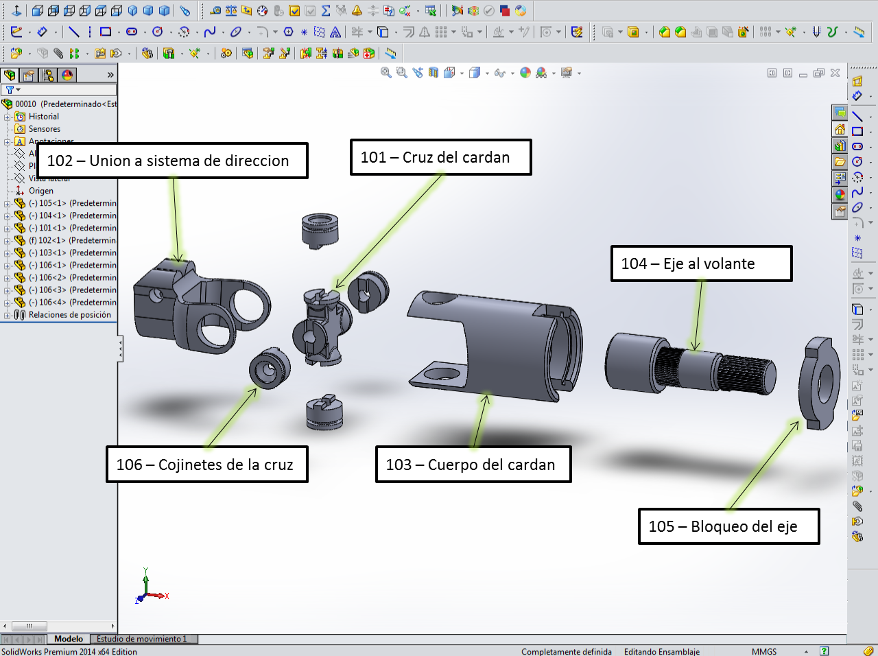
Labeled and numbered components

Each operation for this sub-assembly is defined and named:

Operation N
038_F__Archivos_Web_Orrialdea_Screenshots_power_system_
Components Location
104 – Shaft to the steering wheel

105 – Shaft blocking cap

–> 103 – Cardan joint body
Operation P
040_F__Archivos_Web_Orrialdea_Screenshots_power_system_
Components Location
101 – Cardan joint cross

106 – Cardan cross bushings

–> N
Operation R
043_F__Archivos_Web_Orrialdea_Screenshots_power_system_
Components Location
102 – Joint to the steering system

106 – Cardan cross bushings

–> P

The third sub-assembly is the coonection rod to the wheel:

Vista de seccion de la barra de unión

Section view of the connecting rod

The components are numbered and labeled:

Componentes del ensamblaje

Assembly components

The assembly process is defined:

Operation S
047_F__Archivos_Web_Orrialdea_Screenshots_power_system_
Components Location
204 – Upper bushing

205 – Connecting rod

203 – Bottom bushing

201 – Ball joint to the steering shaft

–> 202 – Ball joint nut

The fourth sub-assembly is the ball joint connecting the rod and the wheel:

Seccion de la rotula

Ball joint sectioned view

The components are numbered and labeled:

Componentes del ensamblaje

Assembly components

The assembly process is defined:

Operation T
051_F__Archivos_Web_Orrialdea_Screenshots_power_system_
Components Location
304 – Ball joint shaft

305 – Bushing

302 – Bushing cap

303 – Dustproof cap

–> 301 – Ball joint body

In the first sub-assembly the steering shaft, the hydraulic cylinder, the cylinder seals and the shaft pusher are set up. In this operation the shaft must be displaced not to collide with the turning shaft. The components are labeled and numbered:

Componentes del ensamblaje

Assembly components

Componentes del ensamblaje

Assembly components

The assembly process is defined:

Operation V
065_F__Archivos_Web_Orrialdea_Screenshots_power_system_
Components Location
20 – Inner seal

24 – Shaft piston seal

–> 18 – Steering shaft
Operation W
059_F__Archivos_Web_Orrialdea_Screenshots_power_system_
Components Location
V

19c – Push bushing

19b – Pusher

19a – Pusher spring

19 – Pusher cap

21 – Nut

–> M
Detalle mostrando la excentricidad del eje en el montaje y el dentado del eje de giro

Detail showing the shaft eccentricity during the assembly step and the turning shaft teeth

Operation X
 005_I__Archivos_Web_Orrialdea_Screenshots_power_system_
Components Location
22 – Hydraulic cylinder

23 – Outer seal

             –> W

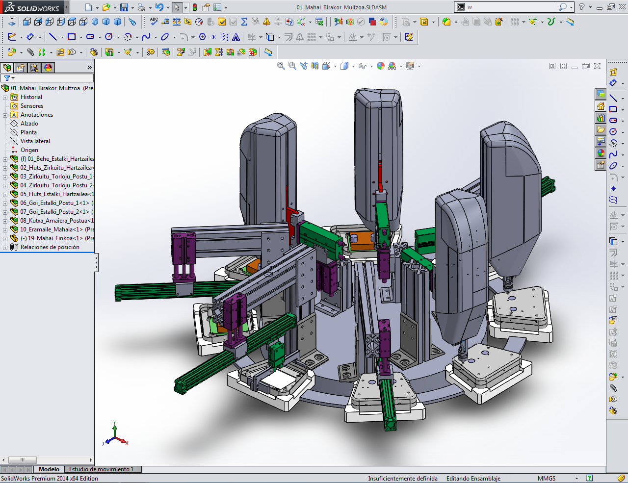
The next step is to mount the connecting rod, ball joint and cardan joint sub-assemblies, toghether with dustproof bellows. This will complete the steering system’s mechanical part, except for the pipes and the pieces which fix it to the chassis:

Steering system components

Steering system components

The assembly process is defined:

Operation Y
071_F__Archivos_Web_Orrialdea_Screenshots_power_system_
Components Location
R

S

T

25 – Dustproof bellow

–> W

The rest of the components are considered as auxiliary, so they are not going to be mounted in the same assembly line.

Montaje finalizado

Finished assembly

With the process defined, the next step is to decide the exit frequency of finished assemblies from the line, design the layout of the assembly line and design the necessary machines and tools for the assembly process.

SolidWorks CAD: Designing a transfer machine, Part 2

In this post the finished transfer machine is shown, lacking a few components:

In the suction cap mechanisms a plastic piece has been added, in which plastic foam blocks are glued, acting as a cushion to prevent the piece movement.

Plastic support and foam blocks in one of the stations

Plastic support and foam blocks in one of the stations

In the extracting station a suction cap mechanism has been implemented to grab the assembled case, identical to the one from the pevious picture.

In the previous post the assembly table was shown this the case-holding supports. A platform has been added, with rails for the transfer ball bearings.

Platform for the case-holding supports

Platform for the case-holding supports

The case-holding support assembly a stop block and a crown gear have been added, the latter being formed by identical segments. The gear will transmit the rotation movement to the assembly. The gear is actuated by a pneumatic indexing table mounting a spur gear.

A single case-holding support, with the crown gear segment and the stop block

A single case-holding support, with the crown gear segment and the stop block

Table assembly with indexing table and its gear

Table assembly with indexing table and its gear

Indexing table position

Indexing table position

The stop block prevents the table from rotating in the station’s assembly phase. The blocking mechanism consist in an actuator with a locking finger which fits in the stop block.

Actuator and stop block view, in locking position

Actuator and stop block view, in locking position

The table assembly and the assembly stations are mounted in a circular base, also acting as a lateral guide for the rotating table. The base is mounted is a steel tube frame.

Circular base view (without the necessary holes) and detail showing the rotating table guiding

Circular base view (without the necessary holes) and detail showing the rotating table guiding

View of the assembly stations and the base mounted on top of the steel tube frame

View of the assembly stations and the base mounted on top of the steel tube frame

The indexing table is also mounted in the steel tube frame.

View of the circular base supports and the indexing table in its support plate

View of the circular base supports and the indexing table in its support plate

An outer protection structure has been designed, to protect the operators from the machine’s moving elements. It is formed by aluminium profiles and steel panels. A cabinet containing the actuator’s electrovalves is located in the lower part of the structure.

Outer structure general view

Outer structure general view

View of the structure without the pneumatic cabinet and the steel panels, showing the octogonal base

View of the structure without the pneumatic cabinet and the steel panels, showing the octogonal base

View of the cabinet, showing the electrovalves and the slots for the pneumatic tubes

View of the cabinet, showing the electrovalves and the slots for the pneumatic tubes

The outer structure is mounted onto the steel frame’s mounting plates.

Steel frame view, with the outer structure mounting plates highlighted

Steel frame view, with the outer structure mounting plates highlighted

The last step is the addition of the conveyors that transport the components and the finished case. The conveyors are commercial products.

Belt conveyor sized for the case

Belt conveyor sized for the case

With the addition of the conveyors the machine’s development os finished, though some details and components have to be defined to be fully functional.

Machine view

Machine view

Machine view

Machine view

Component grabbing and finished case extraction view

Component grabbing and finished case extraction view

Machine view

Machine view

SolidWorks CAD: Designing a transfer machine, Part 1

In this post a transfer machine is designed, which assemblies a control panel, consisting in a two-halved plastic case, and a circuit and screen panel with buttons. The machine must grab each component from different conveyors and assembly them, screwing the circuit panel to one of the halved of the case, and then screwing the two halves.

Front panel view, with the circuit panel assembly holes and the back case

Front panel view, with the circuit panel assembly holes and the back case

Circuit panel views, showing the screen, the front buttons and the back connectors

Circuit panel views, showing the screen, the front buttons and the back connectors

Circuit panel back view, showing the screw holes and the screen conectors

Circuit panel back view, showing the screw holes and the screen conectors

Assembled circuit panel views

Assembled circuit panel views

The assembly process is divided in eight steps:

1- Grabbing the front case and positioning it in the assembly support

2- Grabbing the circuit panel and positioning it in the front case

3- Screwing the 1st and 2nd screws in the circuit panel

4- Screwing the 3rd and 4th screws in the circuit panel

5- Grabbing the back case and positioning it in the front half

6- Screwing the 1st and 2nd screws in the back case

7- Screwing the 3rd and 4th screws in the back case

8- Grabbing and extracting the assembled case

The machine works moving the assembly steps in a circular table, using for the screwing steps the machine presented in previous posts.

General view of the machine

General view of the machine

Upper view of the machine

Upper view of the machine

The machine is in the design phase, so certain elements are missing in every assembly step, and in the whole machine as well. Nevertheless the assembly table and every assembly step is going to be explained:

0- Assembly table:

The assembly table is where the front case is positioned while the other components are assembled. It consists of individual mounting supports joined by arc shaped pieces, founded in ball transfer bearings and keeping centered by means of cylindrical bearings rolling in a cylindrical guide.

Assembly table upper view

Assembly table upper view

Assembly table bottom view

Assembly table bottom view

Assembly table detail, showing the transfer ball bearings and the guiding bearing

Assembly table detail, showing the transfer ball bearings and the guiding bearing

1- Grabbing the front case and positioning it in the assembly support:

This assembly station consists in a gripper mounted on a pistonless actuator, wich moves vertically in a guided actuator. The gripped grabs the front case from a conveyor (not designed yet) and positions it in the assembly table

First assembly station view

First assembly station view

2- Grabbing the circuit panel and positioning it in the front case

This station grabs the circuit panel from a conveyor using a venturi effect vacuum generator and a suction cap. The horizontal and vertical movement of the suction cap is attained using a pistonless actuator and a guided actuator, respectively. A component to prevent the movement of the circuit panel has not been designed yet.

Second assembly station view

Second assembly station view

3 and 4 – Circuit panel screwing:

These stations have screwing machines, with horizontal and vertical movement achieved with guided actuators. Each station mounts two screws at the side of the circuit panel, being the stations identical.

Third and fourth station views

Third and fourth station views

5- Grabbing the back case and positioning it in the front half:

This station grabs the back case using a vacuum actuated suction cap, with the same mechanism as in the second station. This station also lacks a component to prevent the case movement.

Fifth station view

Fifth station view

6 and 7-Back case screwing:

These stations are similar to the 3rd and 4th, with the difference that they only move horizontally, as the screwing machine does not find any obstacle in its movement.

Sixth and seventh stations view

Sixth and seventh stations view

8- Grabbing and extracting the assembled case:

In this station the assembled case is grabbed and positioned in the extraction conveyor. The grabbing mechanism, either by grippers or suction cap, is yet to be designed.

Eighth station view

Eighth station view

The machine is in designe phase, so the blog is going to be updated when finisehd. The next planned steps are: finish the design of the mounting stations, design the table rotation mechanism, define the conveyors and design a protection structure for the machine.

Machine view

Machine view

SolidWorks CAD: Designing an automatic screwing machine, Part 2

The screwing machine design presented in part1 has been completed, with this final design being different from the fourth one presented in the first part. In this fifth and final design the movement of the screw insertion rigid tube and the screwdriver change mechanism have changed.The insertion tube movement has been implemented with a slider. The tube moves when the screwdriver descends and pushes it, using a spring for the return movement (not included in the 3D design).

Vista en detalle de la corredera del tubo de insercion

Detail view of the tube slider

Tubo de insercion, mostrando la superficie que actua a modo de leva para que el destornillador lo mueva

Insertion tube, showing the cam surface where the screwdriver pushes

Video showing the movement of the tube when the screwdriver pushes:

The screwdriver changing mechanism has changed, in order to avoid turning the motor and its support. The motor assembly moves now guided by two guide columns, with their respective bushings, and with the pneumatic cylinder fixed to the machine’s structure. A plastic chain has been added so as to protect the motor’s cables.

Detalle del conjunto motor, mostrando las columnas con sus casquillos

Detail view of the motor assembly, showing the columns and their bushings

Detalle de la conexion entre el piston y el soporte del motor

Detail view of the connection between the cylinder and the motor support

The screwdriver and the motor are connected by an axial coupling. At the bottom of the screwdriver’s hexagonal hole a magnet is placed, which will keep the screwdriver in its position in the coupling.

Vista del acople entre motor y destornillador, con la superficie en la que se encastra el iman seleccionada

Motor and screwdriver coupling, with the magnet’s surface highlighted

Vista general del motor, la cadena para los cables de este y el soporte del atornillador (en rojo), que se usa de conexion para el montaje

General view of the motor, the chain for its cables and the machine support (in red), which will be used to mount the screwing machine to any other machine

For the screwdriver changing procedure, the insertion assembly is designed to rotate.

Vista del conjunto de insercion (seleccionado, en azul) y los cojinetes de giro (en verde)

Insertion assembly view (highlighted in blue), the rotation bushings (in green) and the screwdriver (in yellow)

The screwdriver is connected to the coupling by the magnet and to the insertion assembly by its bearing, so it restricts the free rotation of the insertion assembly. To change the screwdriver, it is separated from the magnet in the coupling and the insertion assembly is rotated.Video showing the extraction process of the screwriver:

Vista general del sistema de atornillado

Screwing machine general view

As a final step a plastic case has been designed, divided in half with an access gate to allow the screwdriver change. The case design does not have a lot of work in it, so it is not a beautiful one. However, it has been taken into account the fact that they will be made by plastic injection moulding.

Views of the machine with its case

The case has a separation between its parts in the back, as an exit for the pneumatic tubes and cables. In addition, the left half case (the one lacking the access gate) has a pad with threaded holes in it, in order to mount the cable protection chain.

Vista de seccion de la carcasa y la cadena, con detalle del punto de montaje de la cadena

Section view of the left case and the chain, with a detail showing the chain mounting position

Vista de la maquina con la puetecilla oculta

View of the machine with the access gate hidden

The gate opens using hinges, and stays closed with a magnet. These details have not been included in the design.

SolidWorks CAD: Designing an automatic screwing machine, Part 1

In this post the design process of an automatic screwing machine is going to be presented. The model is not fully completed, so the final design will be posted when finished.

The system’s function is to automatically put screws. The screws are feeded with a system not included in the design.

The machine is designed around a DIN 965 M3 screw, but it has been parametrized in order to accept different lenght and metric screws.

DIN 965

DIN 965

The design consists of two sub-systems: the insertion assembly and the screwing mechanism. The nozzle design is derived from a design from Stöger.

http://www.stoeger.com/alt/seitene/titele.html

Vista general del mecanismo de la boquilla, para M3

General view of the insertion mechanism, configured for M3

Corte y detalle de la boquilla, para M3

Detailed cut view of the insertion nozzle, configured for M3

The insertion nozzle assembly has been parametrized with respect to the screw metric, so it is possible to work with different metric screws changing the nozzle assembly.

Conjunto de la boquilla, con archivo externo de parametros abierto (M3)

Nozzle assembly, with the external parameter file opened (M3)

Conjunto de la boquilla, con archivo externo de parametros abierto (M8)

Nozzle assembly, with the external parameter file opened (M8)

The screws enter to the nozzle through a flexible hose exiting from the feeding system and connected to the insertion assembly’s rigid tube. The rigid tube displaces to let the screwdriver move. The actual system, using a curved rigid tube and a cam system is not the final design.Video showing the tube and screwdriver’s movement:

The screwdriver pushing mechanism has suffered various design changes.- In the first design a rapid change system was conceived for the insertion assembly, in order to have a wide range of screw metrics for the same pushing mechanism. This idea was discarded, because the screw metrics range available with the change of nozzle was considered enough.

Primer diseño, con el conjunto de insercion resaltado

First design, with the insertion assembly highlighted

– In the second design the mechanism for the movement of the rigid tube was implemented with two moving arms. The design was discarded, it was too complex and showed collision between its elements.

Segundo diseño, con los brazos del mecanismo del tubo resaltados

Second design, with the tube movement arms highlighted

– The third design pretended to transmit rotation to the screwdriver usign a belt and a pulley, and a mechanism to move apart the pneumatic actuator and guides assembly in order to be able to change the screwdriver (that mechanism was not designed). The rigid tube movement was defined with a pair of cams.

Vista general del primer diseño del empujador

General view of the third design

Detalle de la polea, su rodamiento y el destornillador

Detail view, showing the pulley, its bearing and the screwdriver

Detalle del cilindro, columnas guia (con sus cojinetes lineales), rodamiento del destronillador y soporte

Detail view showing the actuator, guide columns (and its bushings), screwdriver bearing and support

Vista del mecanismo del tubo de insercion (resaltado). Una de las levas se ha ocultado para mejor visualizacion

Insertion assembly tube view (highlighted). One of the cams is hided for a better view

– The fourth and current design has the screwdriver extraction mechanism implemented, and a direct transmission of the rotation has been chosen.

Vista general del cuarto diseño

General view of the fourth design

The actuator pushes the screwdriver and the motor. The design has a guide column that works as a support for the actuator, and will also work a a support for the machine, and another column which engages with the motor support when it begins to move. This second column does not engage the motor support in its upper displacement position, allowing the motor support to rotate in order to extract the screwdriver.

Detalle de la segunda columna guia. En esta posicion no restringe el giro del soporte motor

Detail view with the second guide column highlighted. In this position it does not restrict the rotation of the motor support

Video showing the screwdriver extraction process:

The fourth and current design is in process of being finished. The mechanisms allowing the change of screwdriver and the rigid tube movement are going to be finished. In addition, a support for the machine and a case are going to be designed.