The purpose of this simulation was to test the different available restrictions and 2D contacts.

General view of the cutting machine mechanism
Bevel gear cutting machine video:
Mechanism simulation’s front view:
Mechanism simulation’s rear view:
The purpose of this simulation was to test the different available restrictions and 2D contacts.
General view of the cutting machine mechanism
Bevel gear cutting machine video:
Mechanism simulation’s front view:
Mechanism simulation’s rear view:
In this entry a mechanism formed by a cam and lever is going to be simulated. From the simulation the lever’s rotation angle is going to be plotted in a spreadsheet. Afterwards, the spreadsheet data is going to be used as an input for another mechanism formed by a lever and a cam.
Cam and lever mechanism:
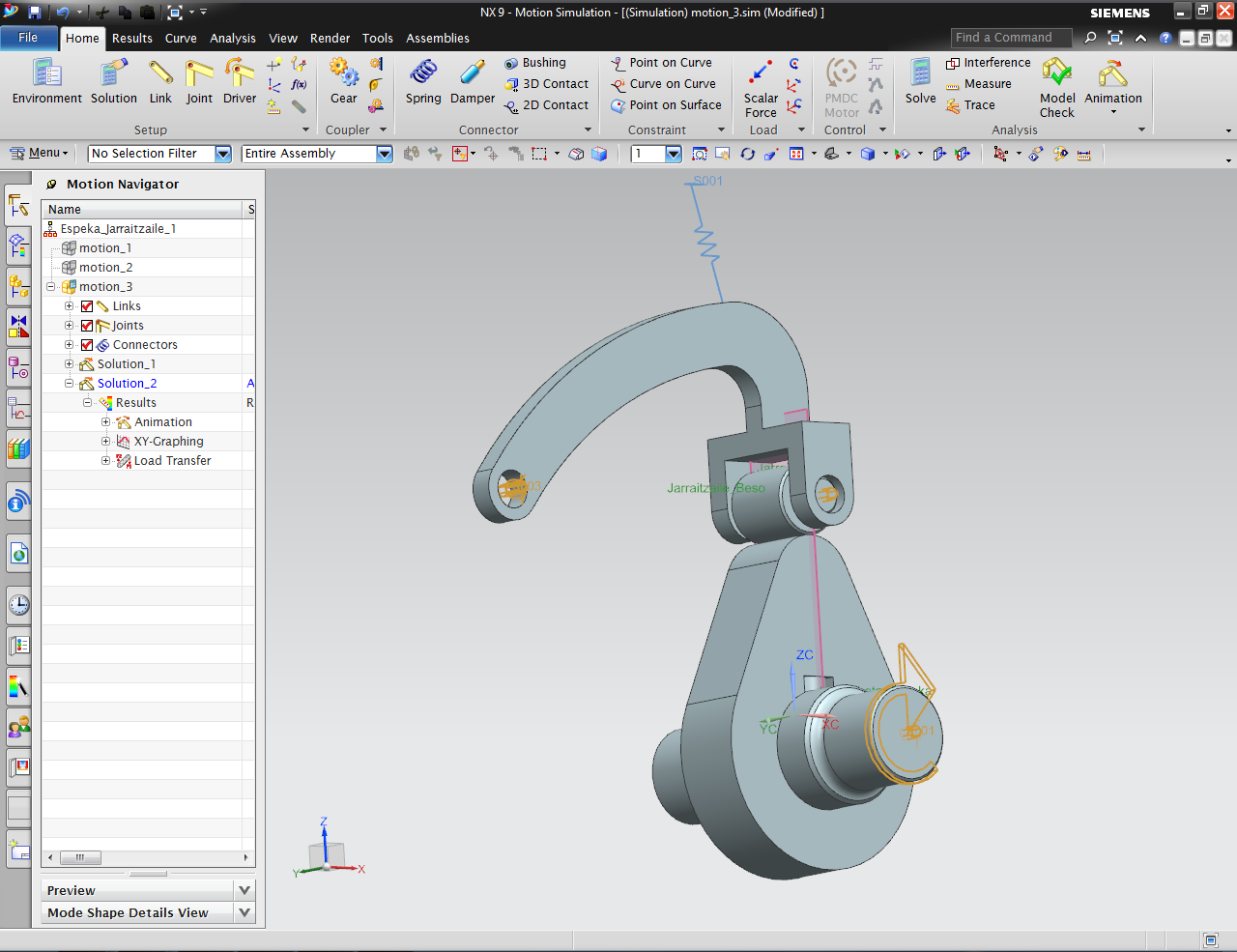
Cam and lever mechanism
The rotation speed is set to 2000rpm:
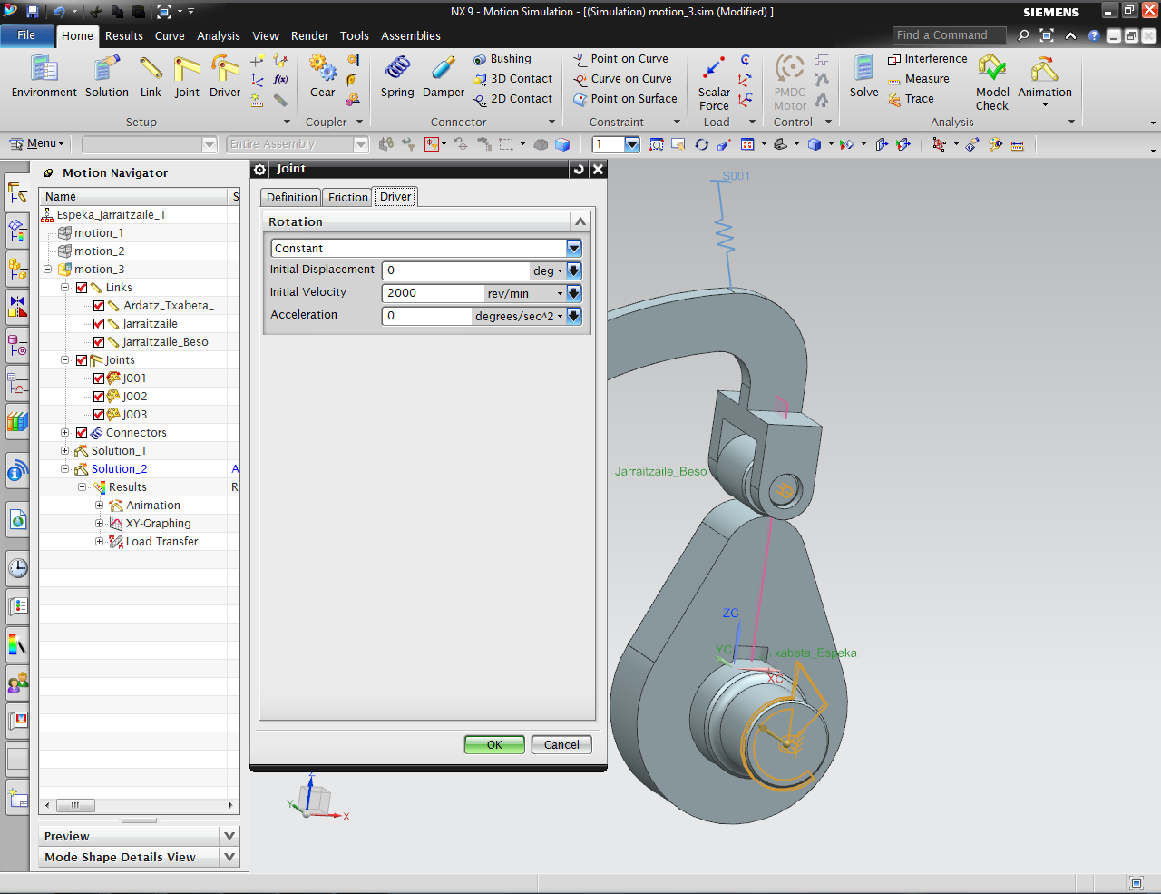
Shaft rotation speed
The cam and the lever’s bearing have a 3D contact relation:

3D contact between cam and bearing
A spring is added to maintain the contact between the cam and bearing:

Spring in the lever
After the simulation is complete, the results for the lever’s angular displacement are obtainded:
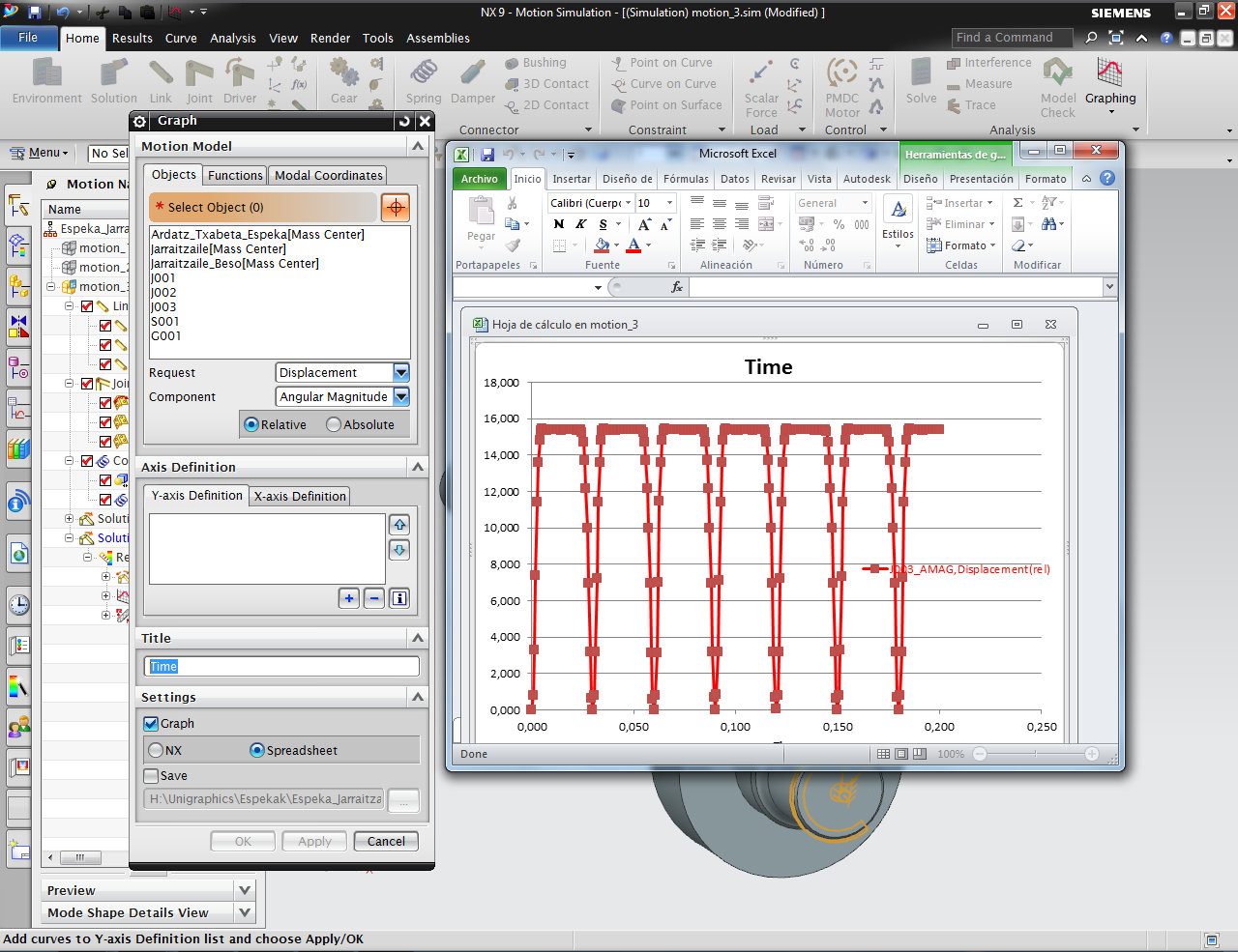
Graph for the lever’s angular displacement

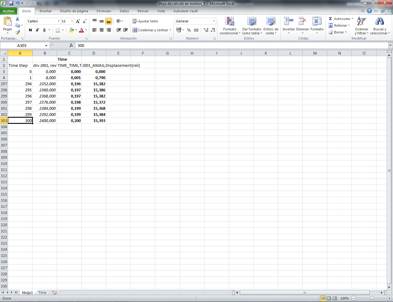
Displacement data spreadsheet
Video showing the mechanism’s simulation:
Once the results are saved, they are going to be used in the lever and valve simulation.

Valve and lever mechanism
The valve has a spring attached to force it to keep in contact with the lever’s bearing:

Valve’s spring
A displacement function is going to be defined as the lever’s input:

Lever’s displacement function definition

New function creation
The increment for the X axis of the function (time axis) will be the time increment obtained in the cam simulation:

Time increment of the previous result
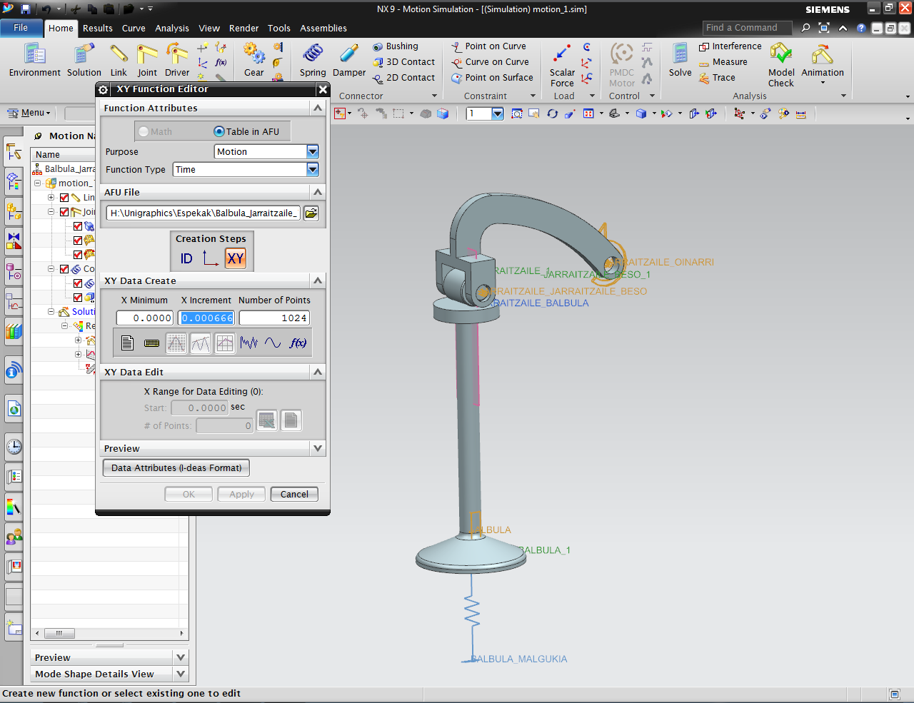
Definition of the increment in the X axis (time)
The function’s step number will be the cam simulation’s result data number:
Previous simulation’s result number

Step number definition
The data spreadsheet is defined:

Data spreadsheet definition

Previous result’s data is copied
The data is going to be edited to take into account the angular phase difference between the two simulations: in the cam’s simulation the starting point is placed at the maximum displacement point, whereas in the valve’s simulation the lever starts at the minimum displacement point. To correct the data the maximum angular displacement value is used:

Maximum displacement value

Spreadsheet data correction
The simulation is computed and it is observed that the contact condition suffers an error. The error is caused by the lever’s initial position, wich causes it to collide with the valve:

Valve and bearing collision
The problem is solved displacing the initial position of the valve:

Modelling initialization
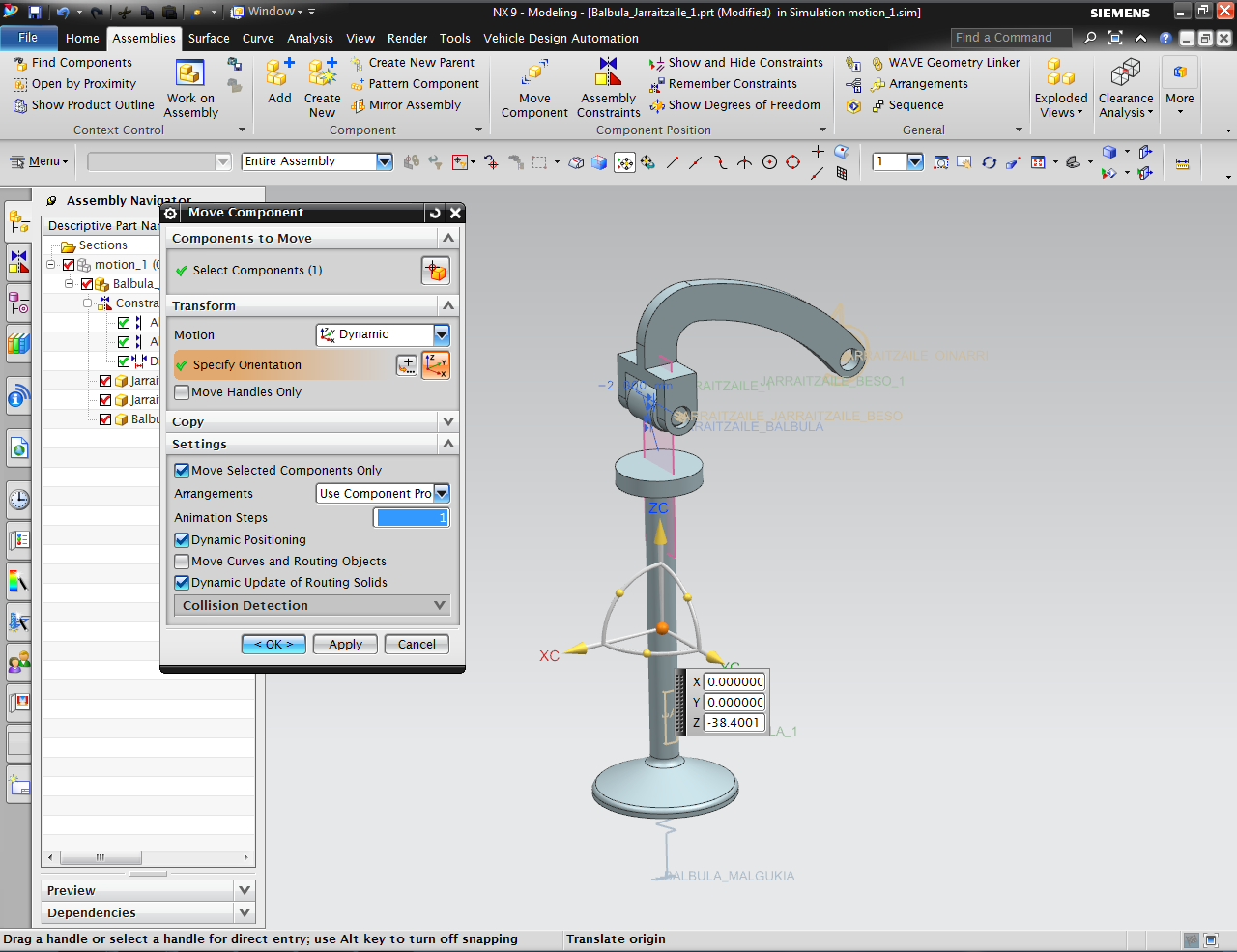
Valve’s initial position displacement
The valve’s spring specifications are modified, taking into account that its free lenght must be longer that the distance separating the valve’s initial position and the bearing’s maximum displacement. The preload and the necessary spring constant for the valve not to lose contact with the bearing are also taken into account:

Valve spring data
Video showing the mechanism’s simulation with the spring data uncorrected:
Finally, once the simulation is computed the valve’s relative displacement data is obtained:

Definition of the data to be graphed
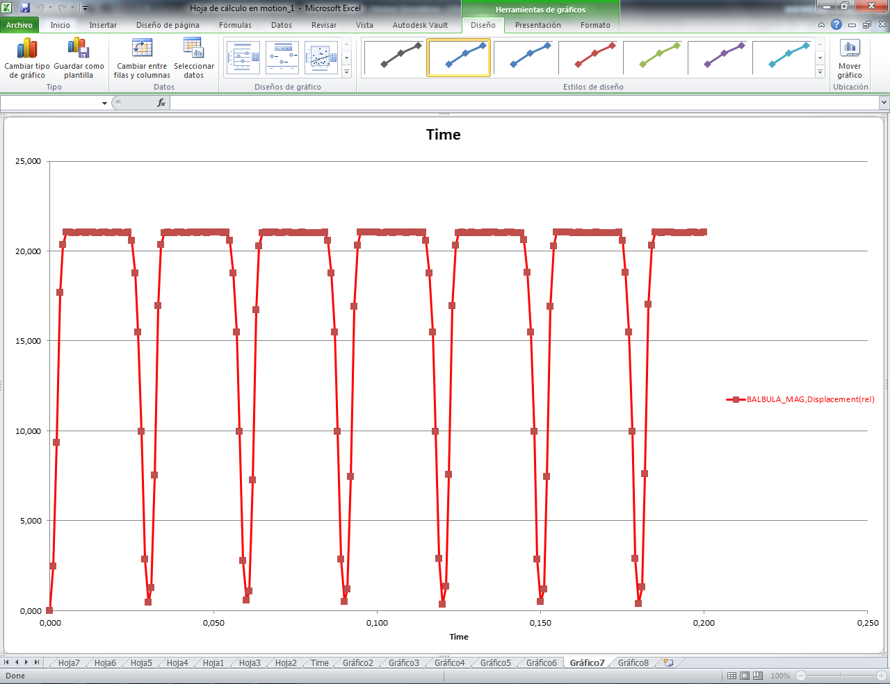
Valve displacement graph
Video showing the mechanism’s simulation with the spring data corrected:
